Optimizing Stage Performance
“How do I best use these parts?” is something that one rapidly runs into in Kerbal Space Program. Should I focus more on the LV-T30 “Reliant”, or LV-T45 “Swivel?” Or for a slightly larger rocket, ditch them both and use the RE-I5 “Skipper”? The answer is “it depends”, but one can use a bit of math to figure out how to use each engine most effectively.
Single Stage
The lego-like nature of KSP rockets give analytic solutions to some design problems! If you assume a fixed mission ΔV and TWR (Well, TMR) requirement, then something surprising happens. For a given engine you can find the maximum payload (if any) it can carry on that mission, and how much fuel said payload needs.
Definition of Terms
Most are self explanatory, but:
\(\Delta V = g_0 \cdot I_{sp} \cdot ln(\frac{m_1}{m_2})\) (The rocket equation is always relevant)
F is the engine’s thrust in the relevant environment.
TWR is Thrust to Weight Ratio (N/N, or unitless)
TMR is Thrust to Mass Ratio (N/kg, or kN/Mg)
R is the mass ratio of the fuel tanks. That is, \(R = \frac{full \ mass}{empty \ mass}\) (unitless, typically 9, but make sure to check)
\(m_{Tankage}\) is the mass of the empty fuel tanks. So for the fully fuelled mass that you see in the VAB/SPH, you’ll want to calculate \(R \cdot m_{Tankage}\). This is typically shown in tonnes or Mg, but some mods (eg: KER) will show it in kg.
Derivation
\(TMR = \frac{F}{m_1}\) (The rocket’s necessary acceleration is defined by its highest mass situation)
\[m_1 = m_{Engine} + m_{Tankage} \cdot R + m_{Payload}\] \[m_2 = m_{Engine} + m_{Tankage} + m_{Payload} = m_1 - (R-1) \cdot m_{Tankage}\]Rearranging the rocket equation: \(e^{\frac{\Delta V}{g_0 \cdot I_{sp}}} \cdot m_2 = m_1\)
Substituting in the values for the initial and final masses: \(e^{\frac{\Delta V}{g_0 \cdot I_{sp}}} \cdot (\frac{F}{TMR} - (R-1) \cdot m_{Tankage}) = \frac{F}{TMR}\)
Solving: \(m_{Tankage} = \frac{F \cdot (1 - e^{-\frac{\Delta V}{g_0 \cdot I_{sp}}}) }{TMR \cdot (R-1)}\) Or \(R \cdot m_{Tankage} = \frac{F}{TMR} \cdot \frac{R}{R-1} \cdot (1 - e^{-\frac{\Delta V}{g_0 \cdot I_{sp}}})\)
And rearranging an earlier equation: \(m_{Payload} = \frac{F}{TMR} - m_{Engine} - R\cdot m_{Tankage}\)
There are, unfortunately, considerable caveats. In particular, the ΔVs, specific impulses, and thrust to mass ratios required for given missions are sometimes known more by preexisting experience than anything directly accessible ingame or via simple calculation.
Note that if you’re launching in atmosphere, you probably want to use a specific impulse typical of 0.2 atm for a single stage. For a 2-stage design, the first should use 0.5 atm and the upper vacuum. These are emperically derived rules of thumb. Also note that you need enough thrust on the pad to overcome gravity, so if you’re using an engine that loses a lot of performance for those first few kilometers…
Perhaps the largest flaw in this is that the tankage mass found here cannot be exactly achieved. If you consider the FL-T100 as the smallest available tank, then empty mass must be a multiple of 0.0625 tonnes, and full mass a multiple of 0.5625 tonnes. ie: precision in final stage mass beyond ~0.5 tonnes is impractical with typical tankage. Keeping part counts down may require still greater deviations.
The payload mass is a partial misnomer, since it is really all of the parts of the rocket that are not engines, tankage, or fuel. This “payload” is not just whatever you want to put into orbit, but also any additional control systems, decouplers, fins, etc. that come along for the ride.
Finally, you can plug in impossible missions to this. It will only be obvious because the payload mass goes negative! Still, this method is useful for sizing (rocket) SSTOs, landers, etc.
Examples
| Role | Engine | ΔV (m/s) | TMR (m/s²) | Tankage (full, tonnes) | Payload (tonnes) |
|---|---|---|---|---|---|
| Early Expendable SSTO | LV-T30 “Reliant” | 3400 (Kerbin → LKO with margin) | 14 | 11.25 | 2.154 |
| Munar lander | LV-909 “Terrier” | 2700 (Low Kerbin orbit → Munar surface → Kerbin) | 5 | 7.875 | 3.625 |
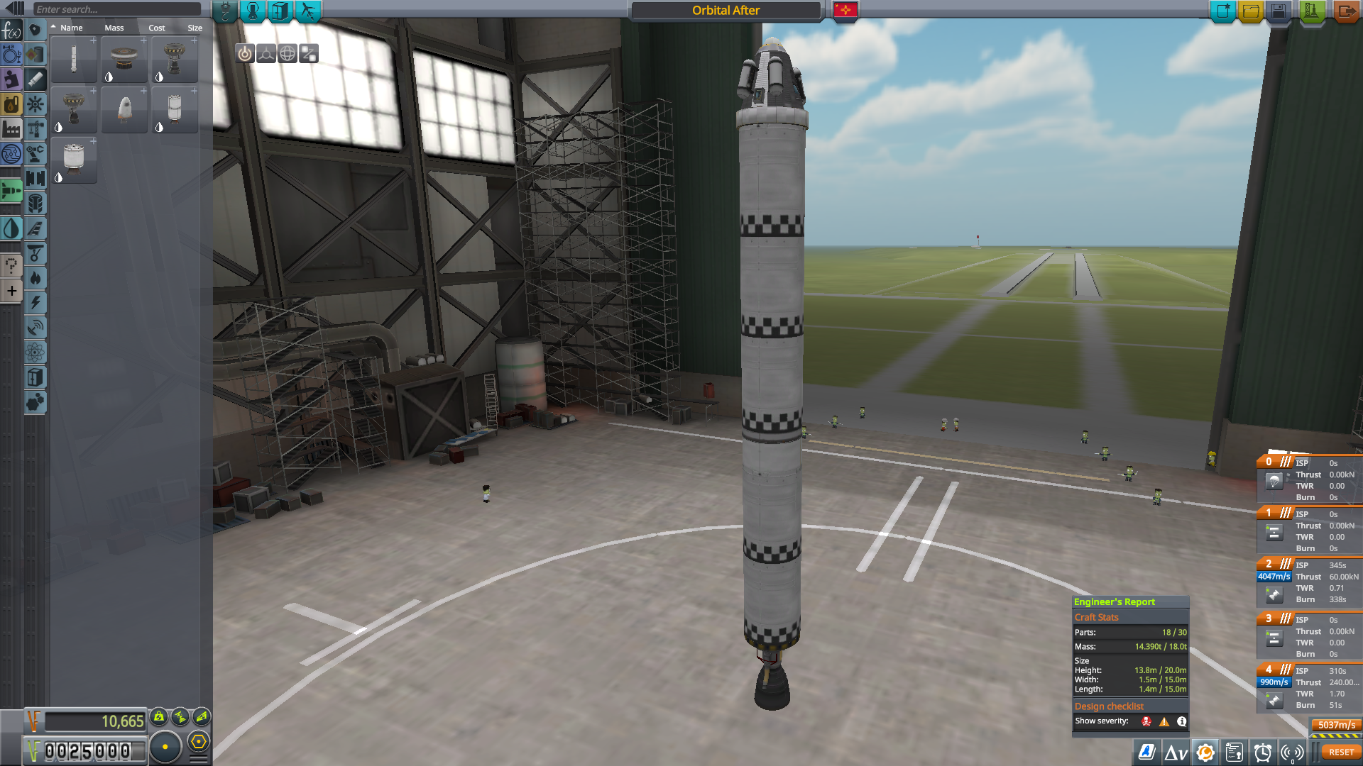
The SSTO as shown is of limited value, but nicely demonstrates an often forgotten aspect of the available design space. (For anyone wishing to reproduce the design, this uses an assumed Isp of 301 s and a thrust of 205 kN)
In rounding the Munar lander went with extra ΔV for better landing site selection. Also note that this is far higher mass than a typical lander design.
Multiple Stage
Fuel Distribution Between 2 Stages
This is somewhat different in that it assumes a mostly-fixed rocket design, and is merely optimizing for ΔV. Note that this is not TWR constrained, and may produce an upper stage incapable of completing the mission. In that case, you can use the maximum weight of the upper stage to define the best useful case. (The overall mass of the rocket is defined by the minimum allowable TWR for for the lower stage, is already defined by the mission requirements.
Since this is not optimizing for minimum mass or maximum payload, it’s mostly just a way to maximize performance for constrained launchers and payloads.
Definition of More Terms
\(E_l\) Engine mass (lower stage)
\(V_{el}\) Effective exhaust velocity (lower stage), equivalent to \(I_{sp} \cdot g_0\) for the engine
\(E_u\) Engine mass (upper stage)
\(V_{el}\) Effective exhaust velocity (upper stage), equivalent to \(I_{sp} \cdot g_0\) for the engine
\(T\) Tankage mass (total mass of empty tanks on both stages combined)
\(P\) Payload mass
\(S\) Additional stage mass. That is, the mass penality for having a seperate stage. In KSP terms this is generally the mass of a decoupler or 3. If you prefer conceptual simplicity this could be rolled into the mass of the lower stage engine.
Calculations
a = \(-V_{el} T^2 R (R-1)\)
b = \(T(E_u+P)(V_{eu}(R-1)^2 - V_{el}(R+1)(R-1))\)
c = \(V_{eu}(R-1)(E_u+P)(E_u+E_l+T+P+S)-V_{el}(R-1)(E_u+P)^2\)
Upper stage fraction of propellant and takage \(= \frac{-b\pm\sqrt{b^2 - 4ac}}{2a}\) (choose whichever comes out positive).
And yes, this is a “real world” use of the quadratic equation.
Examples
Let’s first consider a nominal rocket that one might want to use Kerbin orbit, and flybys (and ideally orbiting) the Mün and Minmus:

Assumptions include: a 1.35 tonne payload, the LV-909 “Terrier” operates entirely in vacuum, and the LV-T30 “Reliant” is constrained to a nominal Isp of 288 s (0.5 atm).

The maximum Δv configuration is probably non-viable due to TWR constraints, so the sort of stage you’d lean towards intuitively is probably better (this will be a theme of this section).
Given the current mass and part count situation, one could argue instead for dropping the tankage slightly and adding an RT-10.
Iterating around with the other engines available at this point on the tech tree:


The lower stages are again using 0.5 atm \(I_{sp}\), rounded to the nearest second. Upper stages are using vacuum \(I_{sp}\).
If one continues to play with values, they can get the classic result of mass ratios approaching being the same as the mass of the fuel tanks come to dominate everything else (assuming that the upper and lower stage have the same \(I_{sp}\)). For differing specific impulses, it is preferrable to have the stage with the higher \(I_{sp}\) (almost always the upper stage) to have a higher mass ratio. The ratio of mass ratios also approaches the ratio of \(I_{sp}\)s for sufficiently tankage dominated rockets, but these are general unachievable within KSP.
Okay, how about larger rockets? Say a Skipper lower stage, a Poodle upper stage, 6 tonnes of payload, and 27 tonnes of tankage?
 on the upper stage.")
This suggests that putting a rockomax X16 on the lower stage and an X32 on the upper stage is actually underfuelling the upper stage. Booster-sustainer configurations due have their problems, though.
The lack of smoothness on this graph is because I’m only considering multiples of the Rockomaxx x800 tank. In any case, the Poodle’s high Isp again suggests something with extremely questionable TWR.
What happens when the Isp is the same? Consider a lower stage of 3x LV-T30s, an upper stage of 1X LV-T30, a payload of 6 tonnes, and 36 tonnes of (filled) tankage. For the purposes of this, both stages will be in vacuum.

This time around, the split is more even in mass, if not Δv. It also suffers less from the TWR problems of the previous craft.
Can this be extended?
Somewhat. The TWR constraints mean that the maximum size of the rocket for any given stage is already well defined. If you are in campaign mode, you may have an explicit mass limit. This does not deal well with the part limit, or details of controllability, though the latter represent a relatively limited portion of the mass of a rocket. Well, barring aerodynamic weirdness or wobbly nightmare that go away as you unlock larger tanks.
There are probably more general analytic frameworks that are possible, but I’m no longer anywhere near as involved in KSP as I was when I did the first versions of these equations (circa 2013-2015). That these also predate the 1.0 release are why I do not particularly consider aerodynamics in general, and fairings in particular.